
Views: 0 Author: Site Editor Publish Time: 2026-10-16 Origin: Site


Processing long aluminum extrusions presents unique operational bottlenecks. Multi-face machining and tolerance accumulation frequently disrupt fast-paced production lines. For manufacturers handling complex architectural or industrial profiles, standard 3-axis systems often require constant manual part repositioning. This repetitive handling inevitably erodes profit margins. It also introduces costly human errors into critical structural assemblies. You need a highly reliable solution to maintain competitiveness.
This guide provides an evidence-based framework for evaluating your machine upgrade options. We help you determine whether moving to a 4-axis system is the correct strategic move for your facility. You will learn how to accurately assess operational realities. We will also help you align machine features with specific production applications. Ultimately, you will gain the insights needed to justify this significant equipment investment.
The tipping point: Transitioning to 4-axis is justified when manual repositioning of long extrusions causes >15% downtime or unacceptable tolerance stacking.
Application sweet spot: The technology is purpose-built for multi-face processing of linear parts, notably in a 4-Axis Aluminium Curtain Wall Facade CNC Machining Center setup.
Customization is critical: Bed lengths, pneumatic clamping zones, and software integration must be tailored to specific profile geometries to realize true ROI.
Implementation reality: Adopting 4-axis technology requires a step-up in CAM programming capabilities and careful attention to collision avoidance during the A-axis rotation.
Manufacturers rely heavily on 3-axis routers for standard flat-plate work. However, they severely underperform when processing multi-sided extrusions. You quickly discover hidden costs when producing long structural profiles. Here are the three primary ways legacy systems fail:
Labor costs inflate rapidly due to constant manual intervention.
Tolerance stacking ruins final assembly geometries.
Bottlenecks throttle your overall factory throughput.
The Cost of Manual Intervention
Every operator interaction increases your production costs. Your staff wastes valuable labor hours unlocking, rotating, and re-clamping 3-meter to 7-meter extrusions. These manual resets halt spindle rotation entirely. They cause machine downtime to skyrocket. When operators manually flip heavy parts, cycle times double. You lose precious production capacity every single shift.
Tolerance Stacking Risks
Manual part rotation introduces profound quality control risks. Every manual rotation on a 3-axis machine creates minute misalignments. These small errors compound rapidly. They become critical flaws in structural assemblies like curtain walls. A half-millimeter deviation on one face magnifies across a 7-meter span. This tolerance stacking causes catastrophic assembly failures downstream.
Throughput Limitations
Single-face processing heavily restricts your scaling capability. During high-volume contract fulfillment, bottlenecks appear rapidly. You cannot meet tight deadlines if machines sit idle during manual flips. Facilities often hit a hard production ceiling. You cannot simply add more shifts to solve this fundamental workflow issue.
You must evaluate your machine strategy pragmatically. Not every facility needs compound multi-axis capabilities. Let us examine the actual production differences between these systems.
3-Axis vs. 4-Axis
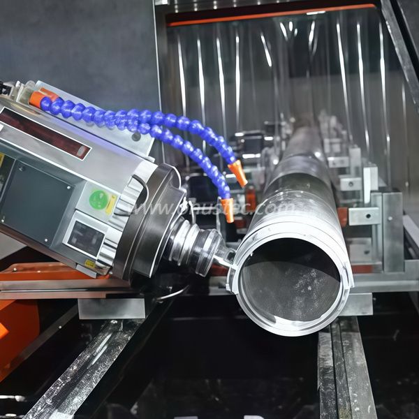
Use a strict decision lens here. A 3-axis setup definitively wins for flat-plate aluminum routing. It remains highly cost-effective for 2D sheet processing. However, a 4-axis system is required when machining three or four sides of a tubular profile. It allows continuous processing of complex profiles. The spindle typically rotates from +90° to -90° automatically. This eliminates the manual flipping forced by 3-axis systems.
4-Axis vs. 5-Axis
You might wonder if 5-axis is superior. Apply the decision lens carefully. A 5-axis system offers unmatched compound angle machining. However, it carries a 30% to 50% higher capital cost. It also requires a significantly steeper programming learning curve. A 4-axis machine provides the optimal balance of speed, cost, and capability. It easily handles 95% of standard facade and window or door profiles.
Machining Strategy Comparison Chart
Feature | 3-Axis Strategy | 4-Axis Strategy | 5-Axis Strategy |
|---|---|---|---|
Part Handling | Manual repositioning needed | Automatic A-axis rotation | Full simultaneous rotation |
Best Application | Flat plates and sheets | Linear tubular profiles | Complex aerospace parts |
Cost Level | Low to Moderate | Moderate to High | Very High |
Setup Time | Very High (Multiple flips) | Low (Single setup) | Moderate |
Upgrading your equipment requires clear application matching. The technology shines brightest when deployed in specific manufacturing environments. A modern machine transforms these particular workflows dramatically.
Modern architecture demands exceptionally precise extrusions. Facilities face the absolute necessity for accurate milling, drilling, and tapping. You must process multiple faces of mullions and transoms flawlessly. Doing this without losing the machine's zero point is paramount. A swiveling spindle achieves this effortlessly. It guarantees structural integrity for massive glass facades. A common mistake here is ignoring thermal expansion during these long machining cycles. Best practices dictate using ambient temperature controls during critical milling phases.
The industrial sector pushes extrusion processing to the limit. We see incredible demand in EV battery trays and aerospace components. Automation rails also require extreme precision. For these components, long and continuous processing is non-negotiable. Any manual interruption risks ruining expensive raw materials. You can guarantee absolute concentricity across multiple faces. This meets the strict standards demanded by the automotive and aerospace sectors.
Many shops struggle with constant product variations. Automatic tool changers (ATC) combined with A-axis rotation provide the perfect solution. They allow rapid changeovers between entirely different profile batches. You can switch from a heavy structural beam to a delicate window frame in minutes. This agility keeps your spindles running and your business profitable.
Off-the-shelf solutions rarely optimize your specific workflow. You must design a system strictly tailored to your daily production needs. Let us break down the core configuration elements.
Working Stroke and Bed Length
You must size the X-axis accurately. Common lengths include 3m, 4m, 7m, or fully modular extensions. Match this to your maximum raw extrusion length. You should also include pendular machining capabilities. This dual-zone setup allows operators to load parts on one end while the spindle works on the other. It effectively eliminates loading downtime.
Intelligent Clamping Systems
Clamping long parts requires careful consideration. You must evaluate motorized, programmable vice positioning against manual pneumatic clamps. Motorized clamps slide automatically into position based on the CAM program. This avoids profile distortion and prevents accidental spindle collisions. Manual clamps cost less but require constant operator vigilance.
Spindle Power and Torque Realities
Not all high-speed spindles perform identically. You must match the kW ratings directly to your typical wall thickness. Differentiate clearly between light window profiles and heavy-duty structural industrial aluminum. Light profiles run well on 7kW to 9kW spindles. Industrial structural beams often demand 12kW to 15kW for aggressive material removal.
Software and Industry-Specific CAM
Hardware means nothing without robust code. Ensure the machine control software integrates seamlessly. It must connect directly with industry-standard architectural software. Platforms like LogiKal or SchuCAD are industry mainstays. You might also need custom API feeds for proprietary ERP systems.
Optimal Configuration Parameters
Component | Light Architectural (Windows) | Heavy Industrial (Automotive/Structural) |
|---|---|---|
Spindle Power | 7kW - 9kW | 12kW - 18kW |
Clamping System | Manual or Semi-auto pneumatic | Fully motorized programmable CNC vices |
Cooling System | Standard Micro-drop (MQL) | High-pressure MQL with chip conveyor |
Bed Length | 3m - 4m | 7m+ with pendular dual-zone setup |
Every major technology rollout involves some friction. Understanding these implementation risks helps you avoid costly delays. Prepare your team proactively for these transitions.
The CAM Programming Curve
You must acknowledge the initial training gap. Operators must transition away from basic 2.5D routing concepts. They now need to manage complex rotary toolpaths. They must also understand advanced collision avoidance algorithms. A spinning spindle head introduces new crash risks. Invest heavily in simulation software training before the machine arrives.
Facility and Footprint Requirements
These machines command massive floor space. Address the realistic footprint needed immediately. Do not just measure for the machine chassis. You must account for the safe loading and unloading of 7-meter profiles. Forklifts and overhead cranes require wide operational corridors. Inadequate spacing creates severe safety hazards.
Chip Management and Coolant
Aluminum machining generates massive volumes of swarf. Discuss the absolute necessity of robust swarf evacuation systems. Automated chip conveyors prevent the machine bed from clogging. You also need precise micro-drop lubrication (MQL). This system applies highly atomized oil directly to the cutting tool. It is designed specifically for high-speed aluminum cutting. It keeps parts clean and extends tool life dramatically.
Choosing the right equipment partner dictates your long-term success. You must look far beyond standard promotional brochures. Demand evidence of performance.
Require a Time Study
Do not buy based on paper specifications alone. Require prospective vendors to run a live simulation. Send them the CAD file of your most complex profile. Make them prove the actual cycle time reduction. A proper time study reveals software glitches and true spindle capabilities.
Service and Spindle Replacement
Machines inevitably break down under heavy daily use. Assess the vendor’s Service Level Agreements (SLAs). Investigate local technician availability in your region. You must also understand the cost and lead time of critical parts. Ask specifically about replacement spindles and A-axis servo motors. Lengthy downtimes will destroy your production schedule.
Financial Assessment
You must build a rock-solid business case. Factor in the initial capital expenditure against concrete operational gains. Project your annual labor savings accurately. Calculate the massive reduction in scrap rates achieved by eliminating manual part flipping. This strict financial justification will clarify your return on investment quickly.
A modern 4-axis machining center is not merely a faster router. It represents a fundamental structural shift in how linear aluminum profiles are processed. By adopting this technology, you successfully eliminate the core inefficiencies of manual part handling. You protect your profit margins from human error.
For facilities heavily invested in curtain walls, facades, or custom extrusions over 2 meters in length, the situation is clear. The technology transitions rapidly from an optional luxury to a competitive necessity. You cannot scale profitably while manually flipping structural beams.
Take immediate action today. Audit your current scrap rates and log your manual repositioning times. Identify the exact bottlenecks holding back your assembly floor. Then, reach out to trusted equipment engineers for a customized cycle-time analysis. Start building your financial justification now to secure your future capacity.
A: It typically ranges from +90° to -90°, providing 180 degrees of total rotation. This allows machining on the top, front, and back faces without unclamping. Some advanced models offer continuous 360° processing if using rotary chucks. However, most standard profile centers rely on fixed stationary clamps combined with a fast-swiveling spindle head to achieve this.
A: It transforms production by allowing all structural notches, drainage slots, and hardware mounting holes to be machined in a single setup. This approach guarantees absolute geometric relationships between features on different faces. It completely eliminates the tolerance stacking and misalignment errors that plague traditional 3-axis manual rotation methods during final assembly.
A: Generally, no. Machines optimized exclusively for aluminum utilize high-speed, lower-torque spindles running between 18,000 and 24,000 RPM. Steel requires immense torque, highly rigid box-way structural frames, and very low RPMs. Attempting to cut steel on a dedicated aluminum machine risks severe spindle bearing damage and catastrophic tool failure.
A: Depending heavily on your shift structure and production volume, ROI typically falls between 18 to 36 months. This rapid payback is driven by the consolidation of two or three manual workstations into one fully automated center. It is also accelerated by a drastic reduction in material waste and costly rework.


