
Views: 0 Author: Site Editor Publish Time: 2026-09-03 Origin: Site


Multi-setup machining often introduces severe tolerance stack-up issues. It increases operator intervention and artificially inflates cycle times. This is especially true for long or complex aluminum profiles. Transitioning to a one-clamp workflow is a highly effective way to scale production. However, it requires precise alignment between workholding, CAM strategy, and machine capabilities. Doing it right transforms your manufacturing floor. You eliminate excessive manual handling. You also reduce scrap caused by misaligned datum points. This guide provides a technical roadmap for evaluating equipment, selecting fixturing, and planning a single-setup aluminum processing workflow. You will learn how to boost throughput without compromising part accuracy. We cover everything from specialized workholding to collision-aware programming to ensure consistent production success.
One-clamp processing eliminates datum shift errors, reducing scrap rates and reliance on manual re-fixturing.
Success depends on specialized workholding—such as low-profile vises or vacuum systems—that prevents deformation in thin-walled aluminum extrusions.
Equipment selection (3-axis vs. 4-axis) must align strictly with the geometry of the profile and the required production volume.
Upfront investment in collision-aware CAM programming is required to safely maximize tool reach in a single setup.
Traditional workflows often rely on multiple setups to complete a single part. You constantly reposition parts. Every time an operator flips an extrusion, they introduce a tiny positional error. These microscopic deviations compound rapidly. We call this tolerance stack-up. Over a long extrusion, this stack-up leads to rejected parts and wasted material. Operators also waste valuable hours on fixture changeovers. Your spindle sits idle while manual adjustments take place. These hidden costs erode profit margins.
Implementing a one-clamp strategy transforms aluminum cnc machining. We must establish objective metrics to measure this transition's success. Your primary goal is measurable improvement across key performance indicators. We look for the following criteria:
Reduction in overall floor-to-floor cycle time: Eliminating manual flips directly increases daily output.
Improved Cpk (Process Capability Index): Consistent datum referencing ensures features align perfectly every time.
Lower fixture-induced scrap rates: Parts stay secure without undergoing repeat clamping stress.
Aluminum properties demand specific attention during machining. The material boasts excellent machinability. However, it remains highly prone to clamping distortion. Thin walls warp easily. Furthermore, aluminum absorbs and retains heat rapidly. Thermal expansion causes parts to grow during aggressive cutting cycles. Setup reduction minimizes the time a part spends absorbing ambient and cutting heat. Consolidating operations into one setup becomes both highly beneficial and technically demanding. You must manage forces and temperatures perfectly.
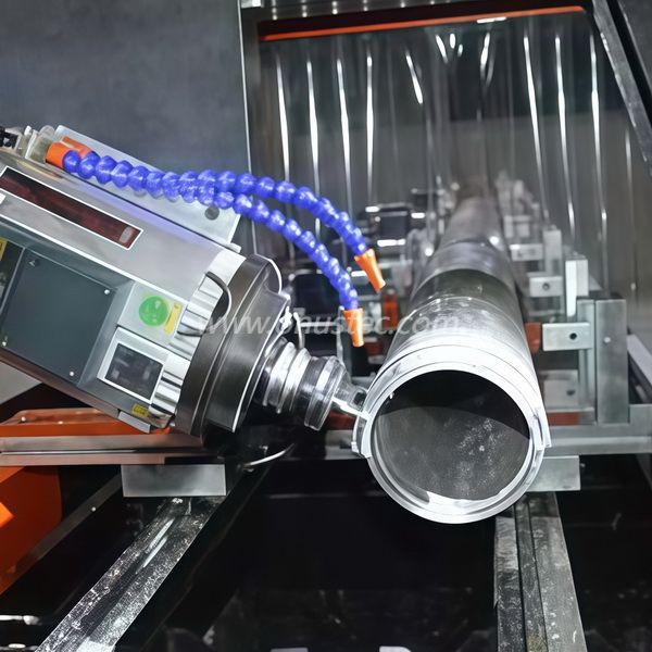
Clamping distortion ruins more aluminum extrusions than poor cutting parameters. Standard vise pressure easily crushes thin-walled profiles. Operators often over-tighten clamps to prevent parts from slipping. This practice warps the metal. When you release the clamp, the material springs back. The carefully machined features suddenly shift out of tolerance. We must address this clamping distortion directly.
Industry experts rely on evidence-oriented solutions to secure delicate extrusions. You need specialized hardware to grip the part firmly yet gently. Consider these proven methods:
Low-Profile Vises: These vises grip only the bottom fraction of an inch of the stock. They maximize tool access to the sides and bottom edges. The spindle moves freely without interference.
Custom Soft Jaws: Machinists cut negative profiles of the extrusion into aluminum or acetal jaws. These custom jaws distribute clamping force evenly across complex contours. They prevent localized crushing.
Vacuum Fixturing & Adhesive Methods: Some architectural plates are extremely thin. Mechanical clamping simply fails. We use vacuum tables or double-sided acrylic tapes to hold these delicate parts flat.
Risk mitigation requires strict operational discipline. You cannot guess how much force to apply. Operators should use torque-limiting wrenches. These tools ensure repeatable setups every single time. Dynamic clamping systems also help. They adjust holding force based on the cutting load. The material must never reach its yield point. Proper workholding guarantees your extrusions remain pristine throughout the machining cycle.
Selecting the right machining center dictates the success of your one-clamp workflow. You must align equipment capabilities strictly with your profile geometry. Standard linear extrusions require a different approach than complex architectural facades.
Sometimes, simpler equipment handles the job perfectly. Identify when a 3-Axis Fast Aluminium CNC Profile Machining Center is sufficient. These machines excel at standard linear extrusions. They handle single-face drilling, milling, and simple industrial frames effortlessly. When evaluating a 3-axis machine, verify several key specifications. Look for rapid traverse rates to minimize non-cutting time. Ensure the spindle RPM supports high material removal rates (MRR). Aluminum loves high speeds—often requiring 18,000 to 24,000 RPM. Finally, check the bed length. Long profiles need extended beds or pass-through capabilities to avoid manual repositioning.
More complex geometries demand advanced kinematics. Identify when a 4-Axis Aluminium Curtain Wall Facade CNC Machining Center is mandatory. Multi-sided architectural profiles require rotation. Complex angles and continuous rotary toolpaths are impossible on standard 3-axis machines without re-fixturing. When evaluating 4-axis solutions, scrutinize the rotary trunnion rigidity. Ensure it handles the leverage of long extrusions. Decide between continuous and indexed 4th-axis capabilities. Continuous motion allows simultaneous multi-axis cutting. Indexed motion locks the part at specific angles. Also, verify heavy-duty chip evacuation systems. Gravity often traps chips in rotated pockets.
Consider scalability and the machine footprint. Assess the available floor space versus your maximum extrusion length. You also need to evaluate the automated tool changer (ATC) capacity. Single-setup operations require a diverse tool library. A robust ATC ensures the machine never stops to wait for manual tool changes.
Comparison of Equipment Characteristics
Feature | 3-Axis Machining Center | 4-Axis Machining Center |
|---|---|---|
Primary Application | Single-face drilling, standard linear extrusions | Multi-sided profiles, complex architectural facades |
Positional Capability | X, Y, Z linear axes | X, Y, Z plus A-axis rotary positioning |
Workholding Complexity | Moderate; straightforward vise or clamp setups | High; requires rotary trunnions or indexed chucks |
Tool Reach Limitations | Limited to top and accessible side features | Excellent; accesses multiple faces in one clamp |
A one-clamp strategy introduces unique programming and physical challenges. Tool reach versus rigidity creates an inherent trade-off. Reaching around low-profile fixtures often requires longer tools. Extended tool stick-out increases the risk of chatter. It also causes deflection when cutting aluminum. We mitigate this by using vibration-damping tool holders. Shrink-fit or hydraulic holders provide superior concentricity and stiffness. You must balance the need to reach side features against the necessity of a rigid cutting setup.
Collision avoidance becomes an absolute necessity. You are asking the spindle to navigate around custom fixtures and trunnions. You must use precise digital twin simulation in your CAM software. Programmers build exact 3D models of the machine, fixture, and stock. The software simulates every movement before the real machine ever moves. This prevents catastrophic spindle-to-fixture crashes. Machining multiple faces in one setup leaves no room for guesswork.
Chip evacuation strategies require careful planning. Single setups often involve deep pockets or rotated geometries. Chips pool inside these cavities. Recutting chips ruins surface finishes and breaks endmills. Program toolpaths that allow chips to clear naturally. Utilize high-pressure coolant to blast debris away. Air blasts work exceptionally well for aluminum, as they prevent chips from adhering to the cutter. Manual intervention should be zero during a fully optimized cycle.
Thermal management is equally critical. Long-cycle single setups generate significant heat. Aluminum boasts a high coefficient of thermal expansion. The material physically lengthens as it gets hot. If you machine a three-meter extrusion without managing heat, the final holes will drift out of tolerance. Manage heat buildup by optimizing feed rates. Keep the chip load high so heat transfers into the chip, not the part. Program cooling pauses if necessary.
Navigating the equipment market requires a structured vendor evaluation framework. You must cut through marketing claims to assess true capability. If you plan a machine purchase, demand rigorous runoff testing. Do not accept tests on standard demonstration blocks. Require them to cut your specific profiles. Verify long-travel positional accuracy using laser interferometry. A machine might hold tight tolerances over 500mm, but drift severely over a 3-meter bed.
If you outsource production, evaluate your machining partners carefully. Request documentation of their workholding strategies. Ask how they combat thin-wall distortion. Review their QA processes for single-setup tolerance verification. A reliable partner willingly shares their process capability data.
Service level and compliance matter immensely. Ensure all equipment meets regional safety standards like CE or UL. Do not overlook aftermarket support. Vendors must offer responsive, localized technical support. Complex 4-axis integrations inevitably require troubleshooting. Waiting weeks for a technician halts your production.
Define immediate action items to move forward. Start by conducting a time-study on your current multi-setup parts. Document the labor hours spent on flipping and re-indicating parts. Calculate the potential return on investment (ROI) based strictly on cycle time reduction and scrap elimination. This data provides the justification needed to upgrade your workflow.
Transitioning to a one-clamp aluminum CNC machining workflow delivers massive operational advantages. It requires higher upfront planning and specialized workholding. You must invest in robust CAM simulation and precision fixtures. However, the ROI in throughput and accuracy easily justifies the effort for mid-to-high volume profile production. You eliminate tolerance stack-up, reduce operator fatigue, and drastically lower scrap rates.
Take the next step toward optimizing your manufacturing floor. Submit a CAD drawing of your most troublesome extrusion to an equipment specialist for a cycle-time estimate. Request a custom workholding consultation to see how low-profile vises can transform your process. Review detailed machine specifications to find the perfect match for your production needs.
A: Chatter prevention relies on rigid workholding and short tool stick-out. Use tailored soft jaws to support the thin walls fully. Upgrade to vibration-damping tool holders like hydraulic or shrink-fit chucks. Finally, optimize your feeds and speeds. Maintain a heavy chip load to stabilize the cutter, and use high-speed dynamic milling toolpaths to reduce radial engagement.
A: A 3-axis machine excels at single-face tolerances. However, multi-sided work requires manual flipping on a 3-axis center. This manual re-indexing increases the risk of datum shift. A 4-axis machine uses rotary positioning to access multiple faces without releasing the part, guaranteeing superior relational tolerances across all machined sides.
A: Standard CNC profile centers typically handle lengths ranging from 3 meters to over 7 meters. For exceptionally long architectural parts, manufacturers utilize machines with extended beds. Some specialized machines feature pass-through capabilities, allowing extrusions longer than the machine envelope to be indexed and machined in sequential segments.
A: Excessive clamping force physically bows or crushes thin-walled aluminum. Machinists cut the features into this distorted state. Once the vise opens, the material experiences a "spring-back" effect. The part returns to its natural shape, but the machined features instantly shift out of tolerance. Precision torque application is mandatory.


