
Views: 0 Author: Site Editor Publish Time: 2026-09-16 Origin: Site


Aluminum is highly machinable, yet it presents unique challenges on the shop floor. This metal is inherently sticky and prone to galling under heat. Generic machine setups often result in poor surface finishes, broken tools, and suboptimal cycle times. Manufacturers frequently misjudge the specific requirements for cutting this material efficiently. You need purpose-built configurations to maximize material removal rates (MRR) without sacrificing precision or increasing scrap. Without the right spindle, tooling, and clamping setup, production lines suffer from bottlenecks and inconsistent part quality.
This guide provides a technical framework for evaluating the critical components of a cnc aluminum milling machine. We focus strictly on matching spindle specifications, tooling geometry, and workholding strategies to your exact production requirements. Read on to discover how you can build a highly optimized machining process.
Spindle choice dictates your production ceiling: high RPM favors light, fast passes (profiles), while high torque is mandatory for deep pocketing in solid blocks.
Tooling geometry matters more than raw speed; prioritizing 2- or 3-flute carbide tools with polished flutes prevents chip packing and built-up edge (BUE).
Aluminum’s malleability requires specific clamping strategies (like soft jaws or vacuum fixtures) to prevent part deformation during heavy material removal.
Selecting between BT30 and BT40 tapers requires balancing the need for rapid tool changes and acceleration against the necessity of machine rigidity.
Machining aluminum effectively requires understanding its unique physical properties. You cannot treat it like mild steel or cast iron. It demands distinct cutting strategies, specific tooling, and tailored machine architectures.
Aluminum alloys possess a low melting point and high ductility. Consider the differences between common alloys. 6061-T6 is highly versatile but relatively gummy. 7075 offers high strength and chips more cleanly. Both share a severe vulnerability to heat. As cutting temperatures rise, the aluminum workpiece softens and reaches a plastic state.
This heat triggers a phenomenon known as built-up edge (BUE). Microscopic particles of the aluminum workpiece micro-weld themselves to the cutting tool. Once BUE begins, it changes the tool geometry rapidly. The tool stops slicing and starts rubbing. This friction generates more heat, accelerating the micro-welding cycle until the tool snaps or the part finish is destroyed.
Many operators mistakenly believe soft metals allow for lightweight machine frames. This is a dangerous assumption. Mitigating vibration remains critical. Cutting aluminum efficiently means pushing feed rates to their absolute limits.
Even soft metals require high dynamic stiffness in Heavy-Duty CNC Machining Centers to prevent chatter during high-speed feed rates. Chatter leaves terrible surface finishes. It also destroys spindle bearings over time. A massive, rigid machine casting absorbs these high-frequency vibrations, allowing your tools to cut cleanly at maximum velocities.
Frame your buying decision around three measurable metrics. Do not rely on generic marketing claims. Evaluate your system based on tangible outcomes.
Cycle Time: Driven primarily by spindle speed, acceleration, and tool engagement.
Scrap Rate: Driven by clamping reliability and machine rigidity holding strict tolerances.
Tool Life: Driven by effective coolant delivery and immediate chip evacuation.
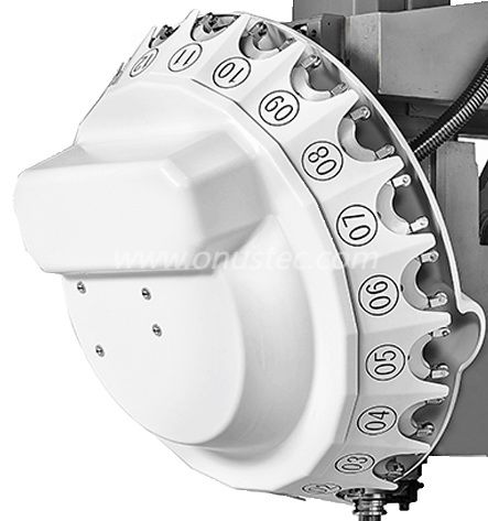
Your spindle dictates the absolute limits of your material removal rate. You must balance rotational speed against cutting force. You cannot optimize for both extremes simultaneously.
Aluminum generally requires extremely high surface speeds (SFM). Because of this, 10,000 to 24,000+ RPM spindles represent the industry standard. High RPM allows you to maintain optimal chip loads when using small diameter end mills.
However, spindle power (measured in kW) must match your cutter diameter. A 24,000 RPM spindle often lacks the low-end torque required to drive a 3-inch face mill. Conversely, a high-torque 8,000 RPM spindle will force you to run tiny end mills at painfully slow feed rates. You must identify your most common tool diameters before selecting a spindle.
The BT30 taper provides incredible agility. It utilizes a lighter tool holder, allowing the machine to perform rapid mechanical movements.
Ideal Use Case: Extrusions, long architectural profiles, and lightweight aerospace components. If your parts require extensive drilling, tapping, or profiling, this is your solution.
Advantages: A 3-Axis BT30 Heavy-Duty CNC Profile Machining Center delivers much faster acceleration and deceleration. Tool change times are exceptionally short. The lighter spindle mass reduces thermal growth, keeping tolerances tight during long production runs. It excels at high RPM operations.
Limitations: The BT30 taper lacks the low-end torque and radial rigidity for running large face mills. It will struggle through heavy roughing passes in solid billets.
The BT40 taper offers massive structural advantages for heavy cutting. The larger flange and deeper taper provide substantial gripping force.
Ideal Use Case: Solid billet machining, deep pocketing, and high material removal rate (MRR) applications. If you are hogging out aerospace structural frames from solid blocks, you need this taper.
Advantages: A 3-Axis BT40 Heavy-Duty CNC Profile Machining Center provides superior radial stiffness. It offers the ability to swing larger diameter tools safely. It delivers much better vibration damping for aggressive, deep cuts.
Limitations: The heavier spindle mass means slightly slower rapid traverse rates. Tool change cycles take longer due to the weight of the tooling assembly.
Table 1: Quick Comparison of BT30 vs. BT40 in Aluminum Milling
Specification | BT30 Spindle | BT40 Spindle |
|---|---|---|
Optimal RPM Range | 12,000 - 24,000+ RPM | 10,000 - 15,000 RPM |
Tool Change Speed | Extremely Fast (1-2 seconds) | Moderate (3-5 seconds) |
Max Tool Diameter | Typically under 0.75 inches | Up to 3.0+ inches (Face Mills) |
Primary Application | Profiles, extrusions, light parts | Solid billets, heavy roughing |
Selecting the right cutting tool prevents immediate failure. Tooling geometry matters significantly more than raw machine speed when cutting soft alloys.
Standard steel-cutting end mills often feature four or five flutes. Using these on aluminum is a critical mistake. Two-flute and three-flute end mills serve as the industry standards for aluminum.
Fewer flutes provide much larger chip valleys. Aluminum chips are voluminous and curly. They need space to evacuate the cutting zone. If you use a four-flute tool, the tight valleys trap the chips. The chips pack tightly, weld together, and snap the tool instantly. A three-flute tool offers the best compromise. It provides excellent chip evacuation while maintaining a thick enough core for rigidity.
We recommend high positive rake angles. You want the cutting edge to shear the material cleanly rather than pushing it. Pushing creates friction and heat. Shearing cuts efficiently and transfers the heat directly into the chip.
Steep helix angles are equally critical. Look for tools featuring 35° to 45° helixes. A high helix angle acts like an auger. It pulls the chips up and out of deep pockets quickly, preventing recutting.
Tool coatings interact chemically with your workpiece. Selecting the wrong coating guarantees ruined parts.
Recommended: Uncoated (highly polished) carbide tools work exceptionally well. The mirror finish allows chips to slide off effortlessly. If you want a coating for extended life, choose ZrN (Zirconium Nitride) or TiB2 (Titanium Diboride). Both offer extreme lubricity.
Warning: Strictly advise against using TiAlN (Titanium Aluminum Nitride) or AlTiN coatings. The aluminum in the coating will bond with the aluminum workpiece through heat. This chemical affinity causes massive built-up edge almost instantly.
Securing an aluminum part presents a unique challenge. You must hold it tightly enough to withstand aggressive roughing, but gently enough to prevent crushing it.
Aluminum yields easily under pressure. Highlighting the danger of overtightening standard vises on thin-walled aluminum parts is crucial. If you clamp a hollow profile in a standard steel vise, the jaws will bow the material inward.
You might machine the exposed face perfectly flat. However, once you unclamp the part, the material springs back to its natural state. Your perfectly flat machined surface immediately becomes curved. This dimensional inaccuracy scraps the part.
To combat deformation, operators implement machined soft jaws. You typically machine these from aluminum or machinable plastic.
Instead of gripping the part at two narrow points, you mill a pocket into the soft jaws that perfectly mirrors the part's geometry. The soft jaws encapsulate the part. This strategy distributes the clamping force evenly across a massive surface area. You can hold the part securely without risking localized crushing or bowing.
For large, flat aluminum plates or long extrusions, standard vises fail completely. They restrict tool access and cause bowing across long spans.
Evaluate vacuum tables for flat sheet work. A vacuum system holds the part down evenly across its entire footprint, leaving the top and edges completely exposed for machining. For structural components, evaluate modular zero-point clamping systems. These allow you to mount custom fixtures outside the machine and swap them in seconds, drastically reducing setup time.
A high-performance spindle and sharp tooling mean nothing if you cannot remove heat and chips from the cut zone. The peripheral systems dictate your true production capability.
Aluminum requires aggressive chip clearing to prevent recutting. Recutting a hardened chip destroys the tool edge. You must choose the right coolant strategy.
Minimum Quantity Lubrication (MQL) uses compressed air mixed with a tiny fraction of oil. It blasts chips away while providing just enough lubricity to prevent galling. MQL keeps the shop clean and avoids thermal shock on the tool. Alternatively, high-pressure flood coolant literally washes chips out of deep pockets. Flood coolant excels during heavy roughing, but requires robust machine enclosures.
Address common oversights before purchasing your machine. The most frequent failure point is inadequate chip management.
Aluminum chips are voluminous and incredibly light. They float on coolant and pile up rapidly. Standard auger systems often fail to move them effectively. You require high-capacity, heavy-duty chip conveyors specifically designed for high volumes. Furthermore, ensure you have sufficient floor space for peripheral coolant tanks and high-pressure filtration systems. Undersized tanks heat up quickly, degrading coolant performance.
When you evaluate vendors, guide the buying process carefully. Do not accept marketing brochures at face value. Demand empirical data.
Request detailed spindle torque charts to verify power at your required RPM.
Demand verifiable MRR test cuts on the exact aluminum alloy you use in production.
Ask for references confirming machine uptime from facilities cutting similar parts.
Building the right cnc aluminum milling machine configuration requires precision planning. You must align the spindle taper, tool geometry, and workholding directly with the specific geometry of the parts you manufacture. A mismatch in any of these areas creates cascading failures, from broken tools to scrapped components.
Focus on maximizing chip evacuation and maintaining rigidity. Understand when to leverage a BT30 spindle for speed and when to rely on a BT40 spindle for structural stiffness. The next step is validating these concepts in reality. We recommend conducting a time-study or a physical test-cut with a shortlisted vendor. Use a representative part file to validate their cycle time claims and inspect the resulting surface finish quality.
A: Yes, but cycle times will be severely compromised. You will be limited by surface feed rates, making the process uncompetitive for high-volume production. Slow spindles cannot generate the required surface footage for small-diameter tools, forcing you to run at a fraction of the tool's actual capability.
A: Aluminum chips are highly prone to melting and welding back onto the cutting tool or the workpiece, a process known as galling. Recutting these hardened chips dramatically reduces tool life and destroys surface finishes instantly. You must clear chips immediately.
A: It depends on the tool size and your radial engagement. A BT30 is highly rigid for tools under 1/2 inch operating at very high speeds. However, it will suffer severe chatter if tasked with large face-milling operations that are much better suited for a heavier BT40 spindle.


