
Views: 0 Author: Site Editor Publish Time: 2026-08-04 Origin: Site


Are you a mechanical engineer, procurement manager, or product designer? You constantly evaluate manufacturing methods for prototyping and scalable production. Choosing the right path determines your product's market success. Aluminum often emerges as a top candidate.
CNC machining is a subtractive manufacturing process. It removes material from a solid block to reveal a precise final shape. In modern manufacturing realities, aluminum stands out clearly. Its high machinability makes it highly cost-effective for diverse applications. However, achieving tight tolerances is rarely simple. It demands specific tooling, precise machine configurations, and strict thermal management protocols.
We will explore how understanding the mechanical process shapes your design strategy. You will discover how different equipment categories and material constraints dictate product quality. Mastering these elements drives better vendor selection. It also lowers your per-part costs significantly. If you often wonder how does cnc machining aluminum work, this comprehensive guide covers exactly what you need to know.
Material Versatility: Aluminum (especially 6061 and 7075) offers an optimal strength-to-weight ratio and exceptional machinability, significantly reducing cycle times.
Equipment Dependence: Part complexity and volume dictate the equipment—ranging from a standard 3-axis high-speed CNC machining center for aluminium to complex 5-axis mills and specialized CNC profile machining centers.
Cost Drivers: Setup times, complex geometries requiring multiple workholdings, and tight tolerances drive up costs more than the raw material itself.
DFM Realities: Designing for standard tooling and factoring in thermal expansion during aggressive material removal are critical for quality control.
Subtractive manufacturing relies on precise mathematical instructions. You start with a raw aluminum block, known as a billet. Engineers use CAD (Computer-Aided Design) software to create a 3D model. Then, CAM (Computer-Aided Manufacturing) software translates this model into G-code. This G-code controls the machine's motors. It dictates exactly where the cutting tools move. The tools spin at high speeds, shaving away excess metal until the final geometry remains.
Aluminum is relatively soft compared to steel. This softness creates unique chip formation dynamics. As the tool cuts, it generates small metal shavings called chips. If you fail to manage chip evacuation, the metal can weld itself to the cutting tool. We call this a "built-up edge" (BUE). BUE ruins surface finishes and quickly breaks expensive cutters. To prevent this, machinists use specialized carbide tooling. They typically select 2-flute or 3-flute end mills. These tools provide large valleys between the cutting edges. Wide valleys allow the bulky aluminum chips to escape efficiently.
Thermal dynamics present a major risk factor. Aluminum possesses a high thermal coefficient of expansion. It absorbs heat quickly and expands measurably. Aggressive machining generates significant friction and heat. If the part gets too hot, it expands during the cutting process. The machine cuts the expanded material to the correct dimension. Once the part cools, it shrinks. It will then warp entirely out of tolerance. Preventing this requires precise coolant strategies. Flood coolant or minimum quantity lubrication (MQL) keeps the material stable. Machinists must also optimize feed rates to transfer heat into the chip, rather than the part itself.
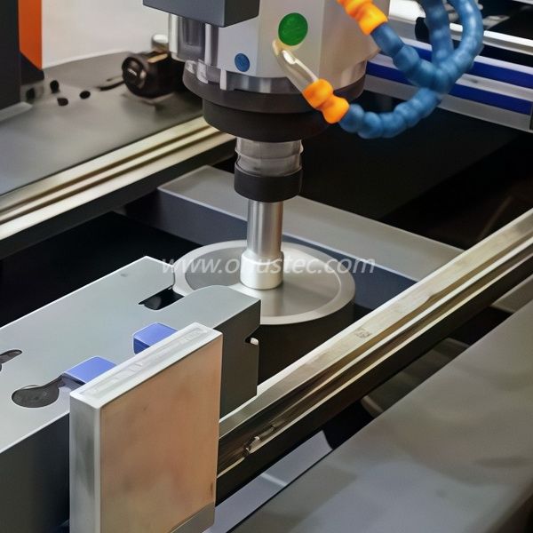
This equipment forms the backbone of modern machine shops. A 3-Axis High-Speed CNC Machining Center for Aluminium moves the cutting tool along three linear axes: X, Y, and Z. It is best suited for flat, 2.5D geometries. Common applications include simple brackets, electronic enclosures, and faceplates.
When you view this through a decision lens, it offers the lowest setup cost. Programming these machines is significantly faster than complex alternatives. Aluminum requires high surface feet per minute (SFM) to shear cleanly. Therefore, high-speed spindles spinning at 10,000 to 30,000 RPM are ideal. They maximize material removal rates without sacrificing finish quality.
These advanced machines add rotational axes to the standard X, Y, and Z movements. They are best for complex aerospace components and organic shapes. They excel at reducing multiple setups. Instead of an operator manually flipping the part, the machine rotates it automatically.
The decision lens here focuses on quality versus hourly rate. You will pay a higher hourly machine rate. However, this offsets costs by eliminating manual repositioning. Every time a human unclamps and reclamps a part, accuracy suffers. Five-axis machining reduces human error. It guarantees tight positional tolerances across multiple part faces.
Specialized applications require specialized footprints. CNC Profile Machining Centers feature exceptionally long machine beds. They are best for extrusions, long architectural components, and structural framing.
Your decision lens here relies on part dimensions. Standard 3-axis mills simply lack the bed length to hold a 10-foot extrusion. These profile centers are essential for high-volume linear parts. They machine multiple features along a continuous length without requiring specialized custom fixtures.
Comparison Chart: CNC Machine Configurations for Aluminum
Machine Architecture | Optimal Part Geometry | Primary Production Advantage | Common Limitations |
|---|---|---|---|
3-Axis High-Speed Mill | Flat, 2.5D, simple enclosures | Low setup cost, fast CAM programming | Requires manual flipping for multiple sides |
5-Axis CNC Mill | Organic shapes, aerospace components | Extreme positional accuracy, single setup | High hourly rate, complex programming |
Profile Machining Center | Long extrusions, structural frames | Extended bed length for linear components | Not suited for small, intricate micro-parts |
Choosing a material is always a trade-off analysis. You must balance mechanical strength against machinability and cost. Rely on industry-standard yield strengths rather than subjective claims.
Alloy 6061-T6: This is the industry default. It boasts excellent machinability and a yield strength around 40,000 psi (40 ksi). It offers good weldability and takes anodizing exceptionally well. It remains the best choice for general-purpose mechanical components.
Alloy 7075-T6: Engineers specify this for high-stress applications. You find it heavily in aerospace and defense. It delivers exceptional yield strength (around 73 ksi), comparable to some carbon steels. However, it is more expensive. It is also less weldable and slightly harder to machine than 6061.
Alloy 5052: This grade is best for sheet metal operations. Shops occasionally machine it for specific use cases. It features high corrosion resistance, making it ideal for marine applications. Unfortunately, it is gummy to mill. It produces long, stringy chips that complicate automated production.
Alloy 2024: This alloy provides excellent fatigue resistance. Aerospace structural components often utilize it. Its main drawback is poor corrosion resistance. It often requires Alclad layers or highly specific chemical coatings to survive harsh environments.
Smart engineering directly reduces manufacturing friction. Design for Manufacturability (DFM) ensures your parts are economical to produce.
Standardizing tolerances is your most powerful cost lever. CNC equipment can hit ±0.001 inches (0.025mm) accurately. However, over-specifying tight tolerances across the entire part is a mistake. It drastically inflates inspection time. It forces the machinist to slow down feed rates. Recommend standard tolerances (±0.005 inches) wherever parts do not mate with other components.
Wall thickness and cavities dictate tool stability. We warn against designing walls thinner than 0.020 inches (0.5mm). Thin aluminum walls vibrate during cutting. This vibration causes tool chatter, ruining the surface finish and destroying dimensional accuracy. Similarly, limit internal cavity depths. Keep depths to a maximum of 3-4 times the tool diameter. Deeper cavities require extended-reach tools. These tools deflect easily and break under lateral loads.
Internal radii cause frequent manufacturing headaches. An end mill is a spinning cylinder. It cannot cut a perfectly sharp 90-degree internal corner. We advise adding generous corner radii to your CAD models. Match these radii to standard end mill sizes. If you demand a sharp internal corner, the shop must use electrical discharge machining (EDM) or specialized broaching. These secondary operations skyrocket your budget.
The machining process is rarely the final step. Surface treatments protect the aluminum and enhance its mechanical properties.
As-Machined (Standard): This finish leaves visible tool marks. Surface roughness typically hovers around 125 µin Ra. It is the most economical choice. It works best for functional internal components where aesthetics simply do not matter.
Bead Blasting & Brushing: Operators blast the part with fine glass beads or brush it with abrasives. This removes tool marks completely. It creates a uniform matte or satin finish. It prepares the surface beautifully for further chemical treatments.
Anodizing (Type II & Type III Hardcoat): Anodizing is crucial for aluminum parts. Type II adds vibrant color and basic corrosion resistance. Type III (Hardcoat) adds significant surface wear resistance. It is essential for sliding or moving parts.
You must account for physical risks during anodizing. Hardcoat anodizing physically grows the part surface. Designers must account for dimensional buildup. A Type III coating typically adds 0.001 to 0.002 inches of thickness. If you have tight-tolerance dowel pin holes, this buildup will ruin the fit. You must specify masking for these critical features.
Not all machine shops possess the same capabilities. Selecting the right vendor minimizes supply chain disruptions.
Quality assurance and compliance form the baseline. If you operate in the aerospace or medical sectors, verify certifications immediately. Demand to see AS9100 or ISO 9001 certificates. Ensure the vendor possesses robust First Article Inspection (FAI) capabilities. They must prove they can measure what they manufacture.
Tooling and CAM expertise distinguish average shops from great ones. A competent manufacturing partner will suggest toolpath optimizations. They utilize advanced techniques like trochoidal milling (dynamic milling). This method maintains constant tool engagement. It reduces heat, extends tool life, and slashes cycle times. Ultimately, these CAM efficiencies lower your final quote.
Evaluate capacity versus scalability carefully. Ensure the vendor’s equipment matches your current lifecycle stage. A small shop with quick-turn 3-axis centers is brilliant for prototyping. However, they will fail during a massive product launch. For volume production, you need a partner with access to automated, pallet-changing 5-axis machines. Match their infrastructure to your future volume needs.
Successful aluminum CNC machining requires a holistic approach. You must balance material selection with intelligent DFM principles. Matching the right machine architecture to your part geometry is equally important.
Aluminum is highly cost-effective, provided you manage thermal expansion and chip evacuation properly.
Machine selection drives unit economics. Align your part complexity with the correct 3-axis, 5-axis, or profile machining center.
DFM guidelines—like standardizing tolerances and avoiding sharp internal corners—drastically lower production hurdles.
Always account for surface treatment dimensional changes during the design phase.
Take action today. Review your current CAD files against standard DFM guidelines. Increase internal radii and open up non-critical tolerances. Contact a manufacturing engineer to request a comprehensive DFM analysis alongside your next quotation.
A: Yes. Aluminum possesses extremely high machinability. This allows for much faster cutting speeds and aggressive material removal rates. It causes significantly less tool wear than steel. These factors drastically reduce overall cycle times and hourly machining costs.
A: High-end CNC equipment can achieve tolerances up to ±0.0005 inches. This requires highly rigid setups, premium tooling, and strict environmental thermal controls. However, the standard precision for most commercial aluminum machining is ±0.005 inches.
A: Yes, it frequently does. Warping occurs due to built-in material stresses and thermal expansion generated by cutting friction. You can mitigate this risk by using stress-relieved temper grades, like T651, combined with proper flood coolant strategies.
A: Yes. However, cast aluminum presents unique challenges. Castings often contain internal porosity and abrasive sand inclusions from the mold. These inclusions can significantly increase cutting tool wear compared to machining standard wrought billet aluminum.


