
Views: 0 Author: Site Editor Publish Time: 2026-04-29 Origin: Site


At the heart of every precision machining operation lies a critical interface. It is the specific point where a sophisticated End Milling Machine meets raw material. While the machine provides the kinematics and torque, the end mill itself dictates the cut quality. A common misconception suggests these tools are merely "fancy drill bits." This is functionally incorrect. Drills are designed for axial hole-making, pushing directly into the material. In contrast, end mills are engineered for radial side-cutting, allowing them to shape complex geometries.
The choice of tooling carries significant financial weight. Companies often invest millions in capital equipment, yet the efficiency of that investment relies on a consumable tool costing significantly less. The selection of the end mill determines cycle time, surface finish, and ultimately, part profitability. This guide covers functionality, strategic selection regarding geometry and material, and advanced operation techniques like High-Efficiency Milling (HEM) for decision-makers.
Radial Versatility: Unlike drills, end mills are designed for side-cutting (profiling, slotting) and can execute complex 3D contours when paired with a 5-Axis End Milling Machine.
Material-Geometry Match: Success depends on matching flute count and helix angle to the ISO material group (P, M, K, N, S); there is no "universal" end mill.
Rigidity Rules: Tool deflection is the enemy. Shorter "stick-out" and variable helix designs are critical for minimizing chatter.
Efficiency Drivers: Modern strategies like High-Efficiency Milling (HEM) utilize the full flute length to extend tool life, shifting the focus from "cost per tool" to "cost per part."
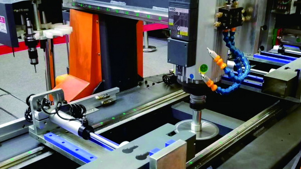
Understanding the end mill requires looking beyond its sharp edges. You must understand how forces apply to the tool during operation. Unlike drills which handle compressive axial forces, end mills must withstand significant lateral deflection forces.
The cutting action of an end mill is primarily peripheral. The side of the tool shears the material as it rotates. This radial engagement allows for profiling and slotting. However, face cutting is also possible. The bottom of the tool can clear flat surfaces, but the primary work usually happens along the helical flutes on the side.
A critical distinction exists between center-cutting and non-center-cutting designs. A center-cutting end mill has cutting edges that extend all the way to the tool's center rotation point. This geometry allows it to plunge vertically into the material, much like a drill. Non-center-cutting mills feature a void in the center. They cannot plunge straight down and will fail if forced to do so. These tools require ramping or pre-drilled pilot holes to enter the material.
The shank determines how the tool connects to the machine spindle. Two main types dominate: Weldon and cylindrical. Weldon shanks feature a flat spot for a set screw, offering a secure hold that prevents the tool from pulling out during heavy roughing. However, this offsets the tool slightly, introducing runout. Cylindrical shanks, used with collet chucks or hydraulic holders, offer superior concentricity. This precision is vital for high-speed finishing operations.
Confusion often arises between end mills and drill bits. The difference lies in load direction. Drills are engineered to handle high axial loads but have weak side-load capabilities. If you attempt to use a standard drill bit for side milling, it will snap almost instantly. End mills feature a thick core and flute geometry specifically designed to resist these radial forces.
Comparison with reamers is also common. Reamers are strictly finishing tools. They size an existing hole to tight tolerances and improve surface finish. They cannot create a hole from scratch. End mills, specifically those capable of helical interpolation, can create holes of various diameters without tool changes. They also shape the exterior of the part, which a reamer cannot do.
The end mill acts as the performance multiplier for the machine tool. A high-end Multi Function End Milling Machine possesses immense structural rigidity. To leverage this, the end mill must remove material at high Metal Removal Rates (MRR). If the tool is weak or poorly selected, the machine's capabilities are wasted. The tool must match the machine’s potential to maximize throughput.
Selecting the right geometry for the specific feature you are machining is non-negotiable. Using a general-purpose tool for every feature leads to suboptimal cycle times.
Square end mills feature a sharp 90-degree corner at the tip. They are the standard for milling flat-bottomed pockets, cutting slots, and defining straight walls. If the design is center-cutting, they can also plunge directly into the stock. Operators choose square mills for prismatic parts where sharp corners and perpendicular walls are required design features.
These tools feature a hemispherical tip ground to a perfect radius. The lack of a sharp corner distributes cutting forces smoothly, making them ideal for 3D contouring. When paired with a 5-Axis CNC End Milling Machine, a ball nose mill can sweep across complex surface topographies, such as turbine blades or molds. They leave a scalloped finish, the height of which is determined by the step-over distance.
A corner radius mill is a hybrid. It is essentially a square mill but with the sharp corners ground to a small radius. This modification significantly increases the strength of the tool tip. Sharp corners are prone to chipping under heavy load. The radius prevents this failure mode. Decision-makers often select these for roughing operations to achieve the best ROI, as the tool lasts significantly longer than a standard square mill.
Roughing mills are easily identified by their serrated, "corn cob" profile. These serrations break the chips into smaller, manageable pieces. This action reduces the radial cutting pressure required. While they leave a rough surface finish, they allow for maximum material removal. They are excellent for underpowered spindles or when large volumes of stock must be removed quickly.
Specialized tasks require specialized geometries. Chamfer mills are designed solely for edge breaking and deburring, eliminating sharp edges on the final part. Drill mills offer a dual-function advantage. They have a pointed tip for spotting and drilling, but also feature side cutting edges for chamfering or light milling. This reduces tool change time, optimizing the cycle.
There is no "one size fits all" in milling. You must match the tool's physical attributes to the material properties.
| Material (ISO Group) | Recommended Flute Count | Coating Recommendation | Primary Goal |
|---|---|---|---|
| Aluminum / Plastics (ISO N) | 2-3 Flutes | ZrN (Zirconium Nitride) or Uncoated | Chip Evacuation |
| Steels / Stainless (ISO P, M) | 4-5 Flutes | AlTiN / TiAlN | Core Strength & Heat Resistance |
| Superalloys (ISO S) | 6+ Flutes | AlTiN / Special Hi-Temp | Rigidity & Surface Finish |
The number of cutting edges, or flutes, dictates chip clearance and core strength. A 2-3 flute design creates large valley channels between the blades. This is essential for Aluminum (ISO N) and plastics. These materials produce large, gummy chips that pack easily. Without space to evacuate, the tool will clog and break.
Conversely, 4-6+ flutes are standard for Steels (ISO P) and Superalloys (ISO S). These materials produce smaller chips but require higher cutting forces. A higher flute count increases the core diameter of the tool, providing the necessary rigidity. Furthermore, odd numbers of flutes (3 or 5) are gaining popularity. They reduce harmonic chatter because the cutting edges do not strike the material in perfect opposition, disrupting vibration patterns.
The angle of the spiral flutes impacts the cutting action. Low helix angles (30° or less) wrap slowly around the tool. They are stronger and better for aggressive interrupted cuts. They also reduce the tendency to lift the part, which is helpful for thin plates.
High helix angles (45°+) provide a faster shearing action. This results in smoother finishes on stainless steel and aluminum and aids in pulling chips up and out of deep pockets. The premium choice today is the variable helix. Here, the spacing between flutes is unequal. This geometry actively disrupts harmonic resonance, allowing operators to take deeper cuts with a 5-Axis End Milling Machine without inducing chatter.
Coatings are not merely aesthetic; they are thermal barriers. TiN (Gold) is general-purpose, older technology. For modern machining, TiAlN or AlTiN (Dark Grey/Violet) is superior. These coatings form an aluminum oxide shield when heated, protecting the carbide substrate. This is required for dry machining steels.
For non-ferrous applications, ZrN (Pale Gold) is critical. It provides a high lubricity (slickness) that prevents aluminum from chemically welding to the cutting edge, a failure known as "built-up edge" (BUE).
Solid Carbide is the industry standard for CNC applications. It offers high rigidity and heat resistance but is brittle. HSS (High-Speed Steel) or Cobalt is tougher and less rigid. While slower, Cobalt tools are viable for older manual machines or unstable setups where carbide would shatter due to vibration.
Even the best tool will fail if the operating parameters are incorrect. Modern CAM strategies have shifted how end mills engage with material.
HEM changes the traditional approach of "deep radial, shallow axial" cuts. Instead, HEM utilizes a small Radial Depth of Cut (RDOC) combined with a large Axial Depth of Cut (ADOC). This technique engages the entire length of the cutting flute rather than just the bottom tip. The benefit is substantial: wear distributes evenly, increasing tool life by 200-300%.
This strategy relies on "Chip Thinning." When you take a very light radial cut, the physical chip thickness decreases. To compensate and maintain a proper thermal load on the tool, you must increase the feed rate significantly. This results in faster cycle times and reduced heat build-up.
How the tool enters the material matters. You should avoid the plunge whenever possible. Vertical plunging forces the tool to re-cut its own chips at the bottom, generating immense heat and pressure. Helical interpolation and ramping are preferred methods. These techniques ease the tool into the pocket on a slope, maintaining a constant chip load and allowing coolant to evacuate debris.
Procurement teams often focus on the price tag of the end mill. However, a cheaper, uncoated tool often costs more per finished part. Frequent tool changes increase machine downtime. Slower feed rates extend cycle times. When utilizing a high-performance 6-Axis End Milling Machine, the cost of the machine hour is high. Using high-tolerance, premium carbide tooling ensures the machine runs at peak efficiency, lowering the total cost per part.
Recognizing failure modes early saves parts and tools. Here are common issues and their remedies.
Symptoms: A distinct screeching sound and a poor, consistent pattern on the surface finish.
Solutions: The primary fix is to shorten the tool stick-out to increase rigidity. Alternatively, increase the feed rate to load the tool properly, or switch to a variable helix geometry to break the harmonics.
Symptoms: Edges become dull rapidly; spindle load meter climbs higher than expected.
Solutions: You are likely running the surface footage (SFM) too fast. Reduce RPM. Also, verify that the coating matches the material hardness.
Symptoms: The tool snaps at the shank or the flutes break off.
Solutions: Chip packing is the usual suspect. The flutes are clogged. Increase coolant pressure or air blast. If slotting, reduce the axial depth of cut per pass.
Symptoms: The part looks rough or has irregular steps.
Solutions: Increase the RPM and decrease the feed per tooth (FPT) specifically for the finishing pass. Ensure you are using a tool with a higher flute count (4 or more) for the final skim.
An end mill is more than a consumable; it is a precision instrument that defines the capabilities of the milling process. The difference between a profitable run and a scrapped batch often lies in the geometry and coating of the cutter. To maximize ROI, move beyond "general purpose" tooling. Matching specific geometries—such as variable helix designs and corner radius profiles—to your specific workload is the fastest way to reduce cycle time.
As a final recommendation, consult with a reputable End Milling Machine Manufacturer or tooling supplier to optimize your setup. Evaluate your current tool life data. If you are changing tools too frequently, consider testing high-performance substrates for your next production run.
A: No, this is dangerous. Drill press chucks are designed for axial force only. The lateral side-load of milling will cause the chuck to loosen, leading to the tool wobbling, flying out, or shattering. It produces poor results and poses a severe safety risk.
A: The main difference is chip space versus core strength. A 2-flute mill has large valleys for clearing gummy chips, making it ideal for aluminum and wood. A 4-flute mill has a thicker core and more cutting edges, providing the strength and finish quality needed for steel.
A: A standard rule of thumb for slotting is not to exceed 1x the tool diameter in a single axial pass. However, utilizing HEM strategies allows for much deeper axial cuts (2x-3x diameter) by significantly reducing the radial engagement.
A: Not for speed or heat resistance. Carbide is superior for high-speed CNC work. However, cobalt is tougher and less brittle, making it "better" for high-vibration setups or older manual machines where carbide would chip or shatter.
A: A center cutting end mill has cutting edges that meet in the exact center of the tool tip. This geometry allows the tool to drill straight down (plunge) into the material. Non-center cutting tools have a void in the middle and cannot plunge.


