
Views: 0 Author: Site Editor Publish Time: 2026-05-06 Origin: Site


End milling is a fundamental subtractive manufacturing process that utilizes a rotary cutter with cutting edges located on both the periphery and the face. Unlike drilling, which primarily cuts axially (vertically) into the material, an end mill is designed to cut radially (side-to-side) as well as axially. This unique dual-cutting capability allows manufacturers to create complex shapes, deep slots, pockets, and intricate 3D contours with high precision. It serves as the backbone of modern machining, enabling the transformation of raw stock into functional components across aerospace, automotive, and medical industries.
The End Milling Machine is the hardware engine driving this process, ranging from manual knee mills to sophisticated CNC systems. However, owning the machine is only the first step. True operational mastery lies in understanding the interplay between tool geometry, coating technologies, and axis configurations. Selecting the wrong variables can lead to chatter, poor surface finishes, and broken tools. In this guide, we explore how to optimize these factors to reduce cycle times and hold tighter tolerances, ensuring you get the most out of your machining operations.
Versatility: End milling combines profiling, slotting, and plunging capabilities, distinguishing it from face milling or drilling.
Tool Selection: Flute count, helix angle, and center-cutting geometry are critical variables for specific materials (e.g., Aluminum vs. Stainless Steel).
Machine Class: Moving from standard 3-axis to a 5-Axis CNC End Milling Machine significantly reduces setup time and improves surface finish on complex parts.
Efficiency: Implementing strategies like High-Efficiency Milling (HEM) and proper stick-out ratios (<3x diameter) lowers Total Cost of Ownership (TCO).
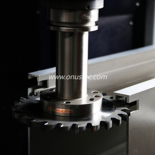
Understanding the physics behind the cut is essential for troubleshooting and optimization. At its core, end milling involves a rotating cutter engaging with a workpiece. The relative motion between the two determines the material removal. In most modern CNC setups, the spindle rotates the tool at high speeds while the table moves the workpiece into the cutter, or the spindle head moves across a stationary part. This kinematic relationship defines the feed rate and cutting speed, which are the primary drivers of productivity.
End mills are distinct because they engage the material in two specific ways. Peripheral cutting utilizes the side of the tool. This is primarily used for profiling (tracing the outside shape of a part) and roughing (removing large volumes of material quickly). Because the cutting forces are directed radially against the side of the tool, this mode is prone to tool deflection if not managed correctly.
Conversely, face cutting uses the bottom (or end) of the tool. This mode is employed for plunging operations or finishing flat surfaces at the bottom of a pocket. The quality of the bottom finish depends heavily on the geometry of the tool’s end teeth and the tram (squareness) of the machine spindle.
A critical distinction that often trips up new operators is the difference between center-cutting and non-center cutting tools. Not all end mills can drill straight down into material.
Center-Cutting End Mills: The cutting edges on the face extend all the way to the center of the tool rotation. This geometry allows the tool to act like a drill and plunge vertically into solid material (Z-axis entry).
Non-Center Cutting (Center-Hole) End Mills: The cutting edges stop short of the center, leaving a small void or relief hole in the middle. If you attempt to plunge with this tool, the center of the tool will hit the material without cutting, causing immediate work hardening or catastrophic tool breakage. These tools require a pre-drilled pilot hole or a ramped entry toolpath.
The process relies on three main hardware pillars. The spindle provides the torque and RPM required to shear the material. High-torque spindles are needed for steel, while high-RPM spindles suit aluminum. The table provides the feed motion and rigidity to hold the workpiece against cutting forces. Finally, the controller is the brain of the operation, translating G-code into precise axis movements. Whether you are using a standard setup or a complex 6-Axis End Milling Machine, the synchronization of these components determines the final part accuracy.
Choosing the right end mill is often a trade-off between strength, chip evacuation, and surface finish requirements. The geometry of the cutter must match the geometric features of the part you are manufacturing.
Square End Mills are the workhorses of the shop floor. They feature sharp 90° corners, making them indispensable for milling flat-bottomed slots, squaring off blocks, and creating sharp internal corners. However, that sharp corner is also the weakest point of the tool and is prone to chipping in hard materials.
Ball End Mills possess a hemispherical tip. They are the standard for 3D contouring, mold making, and die sinking. Because there are no sharp corners, the tool life is generally excellent. When machining curved surfaces, a ball nose reduces the "stair-stepping" effect seen with square tools, though proper step-over (scallop height) calculations are required to achieve a smooth finish.
Corner Radius (Bull Nose) End Mills offer a middle ground. They look like square end mills but have a small radius ground onto the corners. This radius significantly increases the structural integrity of the tool tip, preventing chipping when machining tough aerospace alloys like Titanium or Inconel. They leave a fillet in the bottom corner of a pocket, which is often desirable for reducing stress concentrations in the final part.
The number of flutes on an end mill dictates the balance between chip clearance and core strength.
| Flute Count | Primary Characteristic | Best Material Application | Why? |
|---|---|---|---|
| 2-3 Flutes | High Chip Clearance | Aluminum, Plastics, Non-Ferrous | Large gullets allow gummy chips to escape easily, preventing clogging and re-cutting. |
| 4+ Flutes | High Core Strength | Steel, Stainless, Exotic Alloys | Thicker core resists deflection; more cutting edges allow for faster feed rates in harder materials where chips are small. |
Modern tooling goes beyond basic shapes. Variable helix angles are a premium feature where the flutes are spaced irregularly or spiraled at slightly different angles. This design disrupts the harmonic frequencies generated during cutting, drastically reducing chatter. This is virtually mandatory when milling superalloys. Additionally, roughing end mills (often called "corn cobs") feature serrated edges that break chips into smaller pieces. This reduces cutting forces and allows for aggressive Material Removal Rates (MRR) without overloading the spindle.
Successful end milling requires matching the physical properties of the tool to the material. A cutter designed for plastic will fail instantly in stainless steel, and vice versa.
When machining Aluminum and Non-Ferrous metals, the enemy is the "Built-Up Edge" (BUE), where aluminum welds itself to the cutting edge. To combat this, we use tools with high helix angles (45° or higher) to shear the material cleanly, combined with highly polished flutes or coatings like ZrN (Zirconium Nitride) or TiB2 (Titanium Diboride) that offer low friction.
For Stainless Steel and Superalloys, heat generation is the primary challenge. These materials work-harden if the tool rubs rather than cuts. We require tools with high heat resistance, typically coated with AlTiN (Aluminum Titanium Nitride) or TiAlN. The setup must be extremely rigid to handle the cutting pressure.
Plastics and Composites require sharp shearing action to prevent melting. Single-flute "O-flute" designs are preferred here. They generate minimal heat and provide massive space for chip evacuation, ensuring the plastic remains solid and creates a clean chip rather than a molten blob.
Two parameters dictate the success of the cut: Surface Speed (Vc) and Chip Load (fz).
Surface Speed is the velocity of the cutting edge as it passes the material. It is determined by the tool diameter and the Spindle RPM. Chip Load (feed per tooth) is the thickness of the slice taken by each flute. This is the most critical metric for tool life. If you feed too slowly, the tool rubs against the material, generating friction and heat that burns out the coating. If you feed too fast, the physical force exceeds the tool's breaking strength, snapping the cutter.
Rigidity is king in milling. A common rule of thumb regarding tool overhang is the "3x Diameter" rule. Once the tool sticks out of the holder more than three times its diameter, its rigidity drops by a factor of the length cubed. This creates vibration and poor surface finish. Operators must also balance the Depth of Cut (DoC). For roughing, we prioritize axial depth (Ap), while for finishing, we focus on radial depth (Ae) to manage deflection.
The capabilities of the end milling process are intrinsically linked to the machine architecture. As part complexity increases, manufacturers often migrate from standard setups to advanced multi-axis solutions.
The 3-axis mill is the industry standard. The table moves in X and Y, and the spindle moves in Z. It is best suited for simple prismatic parts, flat slots, and drilling operations. The primary limitation is that working on multiple sides of a part requires manual repositioning (flipping) and re-fixturing. Each time a part is moved, tolerance stack-up errors are introduced, and machine downtime increases.
For complex geometries, the 5-Axis End Milling Machine is the superior choice. It adds two rotary axes (A and B or C) to the standard X-Y-Z motion.
There are two distinct modes of operation here:
3+2 Machining (Positional): The machine tilts the part to a fixed angle and locks the axes before cutting. This allows shorter, more rigid tools to reach deep cavities without colliding with the part walls.
Continuous 5-Axis: All five axes move simultaneously. This is essential for machining impeller blades, turbine components, and complex aerospace contours.
The ROI comes from the "Done-in-One" philosophy. By machining five sides of a part in a single setup, manufacturers drastically reduce setup time and fixture costs while improving overall accuracy.
The evolution continues with the Multi Function End Milling Machine, often referred to as Mill-Turn centers. These machines combine the turning capabilities of a lathe with the milling capabilities of a machining center. A raw bar of stock can be fed in, turned, and then milled with live tooling to produce a completely finished part in one cycle. For shops looking to reduce floor space and Work-In-Progress (WIP) inventory, this scalability is ideal.
In highly specialized sectors, you might even encounter a 6-Axis End Milling Machine configuration, which typically involves a robotic arm or additional rotary tables for intricate undercuts or large-scale composite trimming, though 5-axis remains the standard for high-precision metal cutting.
When selecting a partner, look closely at the End Milling Machine Manufacturer. Key indicators of quality include spindle torque curves (does it have power at low RPM?), thermal compensation features (does the machine correct for heat growth?), and the compatibility of the control system with your existing CAM software.
To remain competitive, shops must move beyond traditional static toolpaths and embrace dynamic strategies that maximize tool life and machine efficiency.
HEM is a strategy that has revolutionized roughing. Traditionally, machinists would take a heavy radial cut at a slow speed. HEM flips this logic. The concept involves using high spindle speeds, a low radial depth of cut (often 10-15% of the cutter diameter), and a high axial depth of cut (using the full flute length). The tool follows a trochoidal (circular) path.
The benefit is twofold: First, it maintains a constant tool engagement angle, preventing shock loads on the cutter. Second, it distributes wear evenly across the entire length of the cutting flute rather than just the tip. This can extend tool life by 200% or more compared to traditional slotting methods.
Total Cost of Ownership (TCO) in end milling isn't just about the price of the end mill. A cheap tool that breaks in the middle of a cycle ruins the part and halts production. TCO analysis involves weighing the cost of premium carbide tooling against the reduction in cycle time and scrap rates. Often, a 5-Axis End Milling Machine combined with premium coated tools offers a lower cost per part due to the sheer speed and reliability of the process.
Chatter: This is the self-excited vibration that ruins surface finish. Causes include long tool overhang or poor workholding. Solutions involve switching to variable helix tools, reducing RPM to find a stable harmonic zone, or improving fixture rigidity.
Deflection: Tools bend under pressure. If you are milling a wall and it comes out tapered, deflection is the culprit. We compensate for this using "spring passes"—repeating the final finish pass at the exact same coordinates with zero offset to shave off the material left behind by the bending tool.
Successful end milling is not the result of a single factor but a synergy between the correct machine axis configuration, precise tool geometry selection, and calculated operating parameters. From the basic mechanics of peripheral cutting to the advanced kinematics of a 5-Axis End Milling Machine, every decision impacts the final quality of the part.
While 3-axis machines handle the basics, the competitive edge in modern manufacturing lies in adopting advanced capabilities. Utilizing strategies like High-Efficiency Milling (HEM) and investing in multi-function equipment allows shops to produce complex parts faster and more reliably. We encourage you to audit your current process parameters, evaluate your tool life data, and consult with specialists to determine if a machine upgrade could unlock new levels of productivity for your business.
A: The primary difference lies in the direction of force and the surface being machined. Face milling primarily uses the bottom (face) of a large diameter cutter to flatten the top surface of a workpiece, directing forces axially. End milling utilizes both the side and the end of the cutter, allowing for radial cutting, slotting, pocketing, and contouring. End mills are generally smaller in diameter and more versatile for complex shaping compared to face mills.
A: Yes, but only if it is a "Center-Cutting" end mill. These tools have cutting edges that meet at the center of the tip, allowing them to plunge vertically into material. Non-center cutting end mills have a void in the center and cannot plunge; attempting to do so will cause the tool to crash. Even with center-cutting tools, chip evacuation is poorer than a standard drill, so peck cycles are often recommended.
A: The number of flutes represents a trade-off between chip space and tool strength. Fewer flutes (2-3) provide large valleys for chips to escape, which is essential for soft, gummy materials like aluminum to prevent clogging. More flutes (4+) increase the core diameter of the tool, making it stiffer and stronger for cutting hard metals like steel, while also providing a better surface finish due to more cuts per revolution.
A: Tools should be replaced based on wear indicators rather than a fixed time. Watch for a degradation in surface finish, an increase in spindle load (amp draw), or a change in the sound of the cut (screeching or crunching). Visually, inspect the cutting edge for chipping or significant flank wear. Continuing to run a dull tool will increase heat, causing work hardening of the part and potential spindle damage.


